Ac Contactor Wiring Diagram
Wiring diagrams include a pair of things: Notesome ac systems will have a blue wire with a pink stripe in place of the yellow or y wire.
Ac Contactor Wiring Diagram Fasco H230a
Timer and contactor wiring diagram pdf.

Ac contactor wiring diagram. Contactors are used to provide this isolation. At the same time, km1 auxiliary contact in the blue box is closed. Ac contactor coil wiring diagram.
And ac contactors are widely used in electric power,. Ac contactor is used in automation panel to control mo. The diagram provides visual representation of an electric structure.
It includes guidelines and diagrams for different types of wiring techniques along with. Basics 13 valve limit switch legend. It reveals the elements of the circuit as streamlined forms, and the power and also signal links between the.
Sometimes, the wires will cross. If it is divided from the function, purpose, and top, the contactor has vacuum, switching capacitor and other types. When this post is grounded the contactor is closed.
Sb2 is the start button and sb1 is the stop button. You may be able to know precisely if the tasks should be finished, which makes it easier for you to correctly handle your time and efforts. On the other hand, the diagram is a simplified version of the structure.
When sb1 is pressed, the motor stops. Wiring a contactor is a safe method for controlling electrical power. Collection of ac contactor wiring diagram.
Ac contactor 4 this diagram is to be used as reference for the low voltage control wiring of your heating and ac system. A wiring diagram is a simplified traditional pictorial representation of an electrical circuit. A wiring diagram is an easy visual representation in the physical connections and physical layout of an electrical system or circuit.
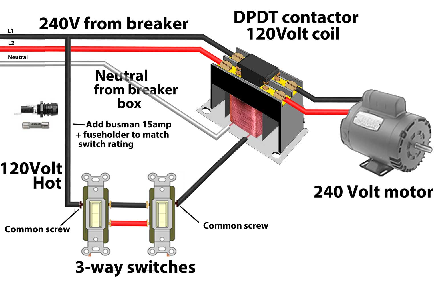
Contactor wiring diagram is explained with its connection. Contactors use 120 volt standard power to energize a magnetic coil, which causes a set of internal contacts to close and provide higher power to the equipment. A wiring diagram is a simplified traditional pictorial representation of an electrical circuit.
The motor is 3 phase and it appears to be wired according to the diagram for the low voltage 220. When sb2 is released, the motor rotates as usual. These voltages must be electrically isolated from the standard 120 volts ac.
After that the main power contactor coil energized due to electromechanical action and this latch contactor poleit applies full line voltage to the motor terminals. 220v ac contactor wiring method and physical wiring diagram brief introduction of contactor if the contactor is divided only from the voltage, there are two types of ac contactor and dc contactor. As stated previous, the lines in a ac condenser wiring diagram represents wires.
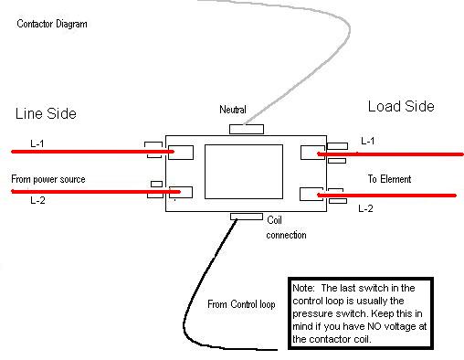
Typically a contactor is activated by a remote switch or other controlling electrical device. Note that one one of the contactor acts as a switch for the start button. If you wire this side to the battery the contactor will not work.
240 volts ac and 480 volts ac are commonly used for these large pieces of. Note some ac systems will have a blue wire with a pink stripe in place of the yellow or y wire. Always refer to your thermostat or equipment installation guides to verify proper wiring.
Function cjx2 ac contactors provide. Always refer to your thermostat or equipment installation guides to verify proper wiring. Collection of ac contactor wiring diagram.
Either of the two start buttons will close the contactor, either of the stop buttons will open the contactor. What is often a wiring diagram? Then screw the ft on the brand new half back on the unit and.
But, it does not imply connection between the cables. Electrical engineering world electrical wiring electricity electrical engineering. 4 pole contactor working is also explained.
Injunction of two wires is generally indicated by black dot at the junction of two lines. Wiring diagrams 55 57 type s ac combination magnetic starters 58 59 class 8538 and 8539 58 59 3 phase size 0 5 58. Contactor wiring diagram pdf download.
There’ll be principal lines that are represented by l1, l2, l3, and so on. Air conditioner contactor wiring diagram | how to working magnetic contactor | single pole or duel pole amresh11 techin this video i will tell you how to wi. Use these tips to learn how to wire a contactor.
The circuit breaker is used for protection against short circuits while the overload relay. Notesome ac systems will have a blue wire with a pink stripe in place of the yellow or y wire. The figure below is the wiring diagram of ac contactor, which can be compared with.
Ac contactor 4 this diagram is to be used as reference for the low voltage control wiring of your heating and ac system. Air conditioning ac contactor control board 1 this diagram is to be used as reference for the low voltage control wiring of your heating and ac. Note some ac systems will have a blue wire with a pink stripe in place of the yellow or y wire.
A wiring diagram is a simplified traditional pictorial representation of an electrical circuit. This contactor draws just under 1a at 14v. Eaton wiring manual 0611 5 2 contactors and relays 5 5 contactor relays contactor relays contactor relays are.
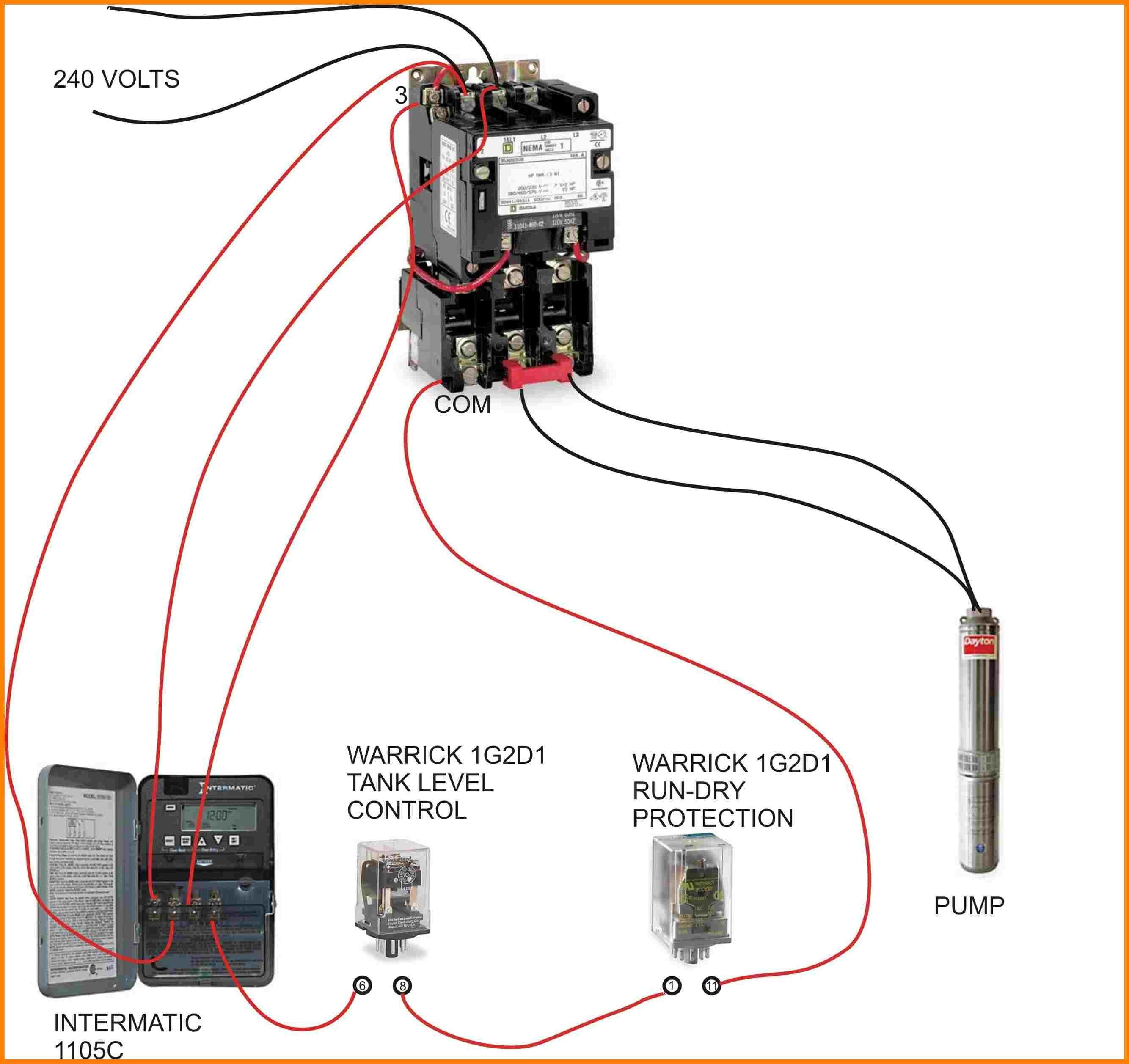
Ac contactor for pump software. A wiring diagram is a type of schematic which uses abstract pictorial symbols showing each of the interconnections of components in a system. Symbols that represent the components in the circuit, and lines that represent the connections together.
When sb2 is pressed, km1 coil is powered on and closed.
47 Contactor Wiring Diagram Single Phase Wiring Diagram Source Online

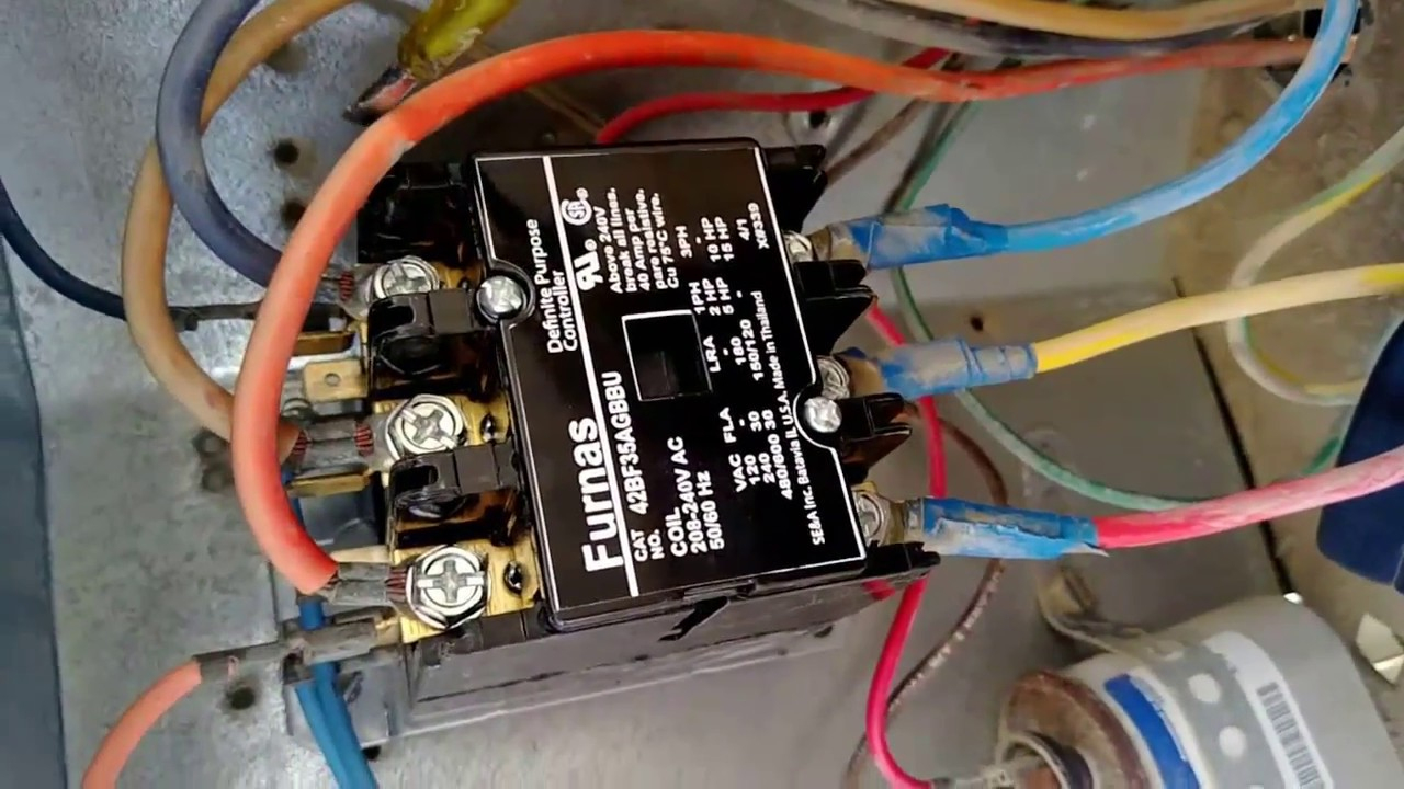
Furnas Contactor Wiring Diagram Download Wiring Diagram Sample
Single Phase Contactor Wiring Diagram A1 A2

Air Conditioner Contactor Wiring schematic and wiring diagram
Ac Contactor Wiring Diagram Fasco H230a
Contactors 240 Volt Contactor Wiring Diagram Wiring Diagram
Only the red and wires are connected on the ac unit but the thermostat has all connected. Is

Physical wiring diagram of CJX2 contactor Knowledge Yueqing Winston Electric Co.,Ltd

New Contactor Coil Wiring Diagram diagram diagramtemplate diagramsample

Single Phase Motor Contactor Wiring Diagram

Contactor Tmc18 Wiring Diagram
Rheem Ac Contactor Wiring Diagram

Single Phase Contactor Wiring Diagram A1 A2

Air Conditioning Contactor Wiring Wiring Diagram Networks
Ac Contactor Wiring Diagram Cadician's Blog
Wiring Diagram 3 Phase Contactor

contactor block Electrical projects, Electrical circuit diagram, Home electrical wiring

Ac Contactor Wiring Diagram Fasco H230a
AC Contactor and Capacitor wiring ? Fan running and breaker flipping.